SẢN PHẨM
Năng lực R&D sản phẩm hàng đầu

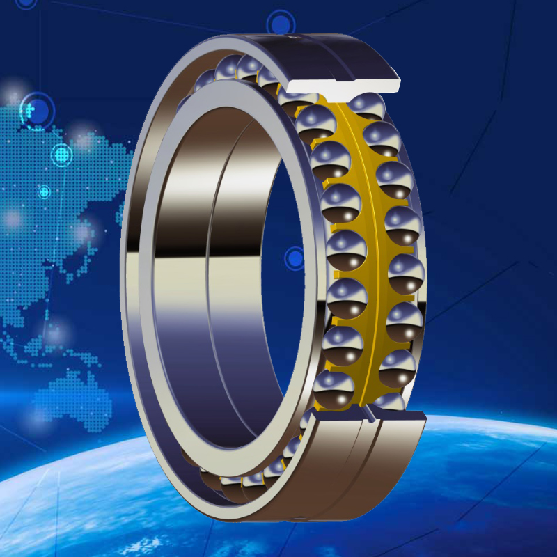
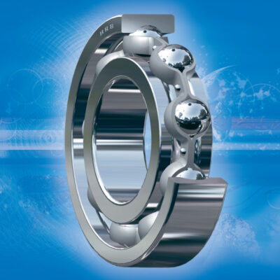
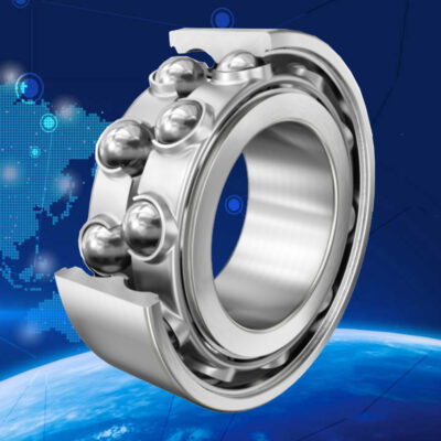
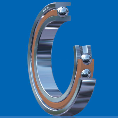
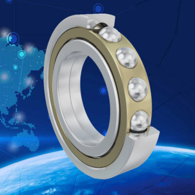
The structure of a HRB double row angular contact ball bearings is similar to a pair of single row angular contact ball bearings arranged in back-to-back, while the of the bearing with a contact angle of 30° is a little narrow than the pair of single row bearings. Due to their high rigidity and non-separable feature, double row angular contact ball bearings can accommodate inclined moments too, design as bellows.
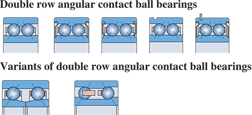
The design of HRB double row angular contact ball bearings has the following variations
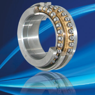
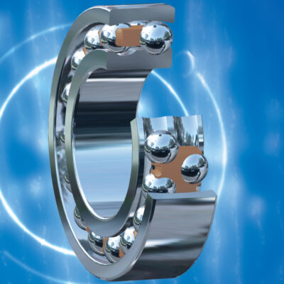
1 . With filling slot on one side, such designed bearings can be filled with a great number of large size balls to take higher radial loads and one direction axial loads, usually mated with pressed steel cage or machined brass solid cage, suitable for lower speed applications.
2. Without filling slot, such designed bearings can therefore take axial loads of the same magnitude in either direction, mated with cage of glass-fibre reinforced nylon 66 or pressed steel cage good at reducing bearing heat generation and running temperature, suitable for the operation at high speeds.
3. Shield(s)(non-rubbing) or seal(s)( rubbing) at both sides or one side is available optionally. The closed bearings are filled with grease of lubrication and rust proof. Unless otherwise specified, 2# lithium base grease is generally used at temperature -30℃ to +100℃. Because of long life grease lubrication, there needs no maintenance. These bearings do not have to be heated or washed prior to mounting.
Bearings with shields are normally used in the place where the inner ring is rotating, or else the filled grease would go out of the bearing in case the outer ring starts a rotation over a certain speed.
In bearings with seals at both sides, the sealing lip contacts in the sealing groove on the shoulder of the inner ring. The seals are made of oil resistance and antiwear rubber, reinforced with steel insert, allowable operating temperatures -40℃ to +120℃. The outer circumferential edge of the seals is locked into the groove on the bore shoulder of the outer ring. The sealing lip exerts a slight force on the inner ring for sealing.
Under severe working conditions such as extremely high speeds or temperatures, the filled grease may escape from inner ring. If such a leakage is prohibited, specified design is available.
Dimensions
The boundary dimensions of double row angular contact ball bearings listed in the bearing tables are in conformity with ISO15, except values for the width of 3200 ATN bearings.
Angular misalignment
For double row angular contact ball bearings, the angular misalignment of the outer ring relative to the inner ring could lead to the additional stress generation between the balls and raceways, so that the bearing life would be shortened.
Tolerances
HRB standard basic double row angular contact ball bearings are manufactured to normal clearance. If necessary, bearings of P6 or P5 tolerances are supplied as well.
Axial internal clearance
HRB basic double row angular contact ball bearings have normal axial clearance. If necessary, bearings with larger or smaller axial internal clearance are also available by HRB. Values for axial internal clearance are shown in Tables 1, for bearings having zero measuring load prior to mounting.
Radial clearance ≈ 0.6 axial clearance
![]()
Cages
HRB basic double row angular contact ball bearings generally have glass-fiber reinforced nylon 66 cages or machined solid brass cages.
Bearings with cage of glass-fiber reinforced nylon 66 are used in the majority of applications at working temperatures -30℃ to +120℃, where the bearings have to work at extremely high speeds or under severe conditions, the pressed steel cages or machined brass cages are preferable. If tailored cages are required, contact HRB technology department.
Mounting guide
When mounting a double row angular contact ball bearing with filling slot, the axial load in one direction or the main axial load should be taken by the ball set in the groove which does not have filling slot.
Minimum rolling bearing load
In order to keep proper running of ball or roller bearings, including double row angular contact ball bearings, the minimum required loads has to act on them, or else during high speed running the mass forces of the balls and cage and the inadequate lubricant resistance may generate a harmful sliding between the balls and raceway, easy to lead to bearing damage.
Considering such a situation, the minimum required load is estimated from the equation:
Frm = kr(γn/1000)2/3(dm/100)2
where:
Frm: minimum radial load, N
kr: minimum radial load factor:
=80, for 32 series bearings
=60, for 32A series bearings
=95, for 33 series bearings
=70, for 33A series bearings
γ: kinematic viscosity of oil at operating temperature, mm2/s
n: bearing speed, r/min
dm: bearing mean diameter
=0.5(d+D), mm
In general, the bearing supporting weight adding the external forces always goes beyond the minimum required load. If not, an additional load has to be exerted, for example, increasing belt tension.
Equivalent dynamic bearing load
Double row angular contact ball bearings with a contact angle of 30°.
P = Fr + 0.78Fa , for Fa/Fr ≤ 0.8
P =0.63Fr + 1.24Fa , for Fa/Fr>0.8
Equivalent static bearing load
Double row angular contact ball bearings with a contact angle of 30°.
P0 = Fr + 0.66Fa
CATALOG VÒNG BI CẦU TIẾP XÚC GÓC HAI DÃY HRB