SẢN PHẨM
Năng lực R&D sản phẩm hàng đầu

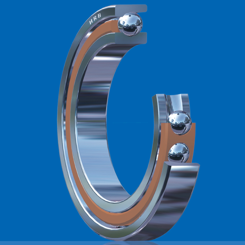
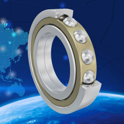
Single-row Angular contact ball bearings
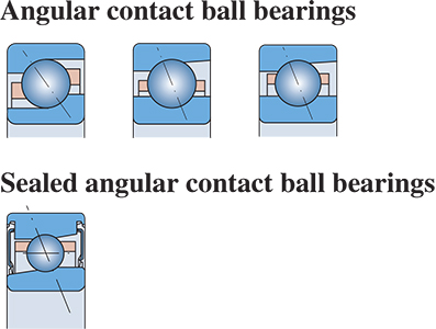
Angular contact ball bearings are especially good for taking combined loads, i.e. simultaneously acting radial and axial loads. The axial load carrying capacity of these bearings increase with contact angle increasing. A bearing contact angle is defined as the angle between a radial plane perpendicular to the bearing axis and the line connecting the two contact points of a ball with the inner and outer ring proves, so that the load resultant is transmitted by one bearing rib to the other alone. Large or small contact angles are indicated by different designation suffixes respectively.
HRB angular contact ball bearings include:
– Single-row angular contact ball bearings
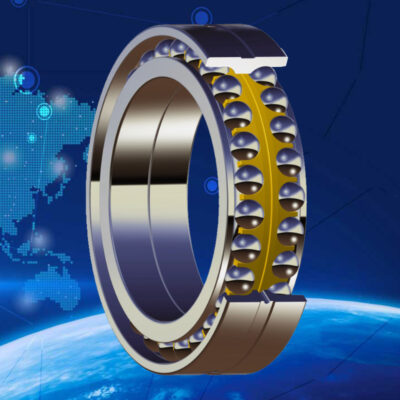
– Double-row angular contact ball bearings
– Four-point contact ball bearings
1. Characteristics
Single row angular contact ball bearings can only take axial loads in one direction. Under the action of a radial load, an axial load would be included on the bearing, which has to be counteracted by an additional force, that is why such bearings are generally paired.
In single row angular contact ball bearings, comparatively more balls are filled, so that they can have more carrying load capability. Three types of contact angles 15, 25 and 40°are adopted, identified by suffixes C, AC and B respectively. Single row angular contact ball bearings are of non-separable design or separable design. Subject to different applications the non-separable bearings are divided into three series normal, high speed and ultra high speed. In some components or units such as magnetic restricted by space conditions, the inner ring with assembly and the outer ring of a separable bearing may be mounted separately, and such bearings are called magnet bearings as well.
As s standard cage design, the cage of the non-separable bearings is of reinforced textolite without any suffix to the bearing designation, see as below:
– TA: Fabric reinforced textolite cage, rided by the outer ring
– TN: Fabric glass reinforced nylon 66 cage
– M: Machined brass cage
The separable bearings (magreto bearings) are mainly fitted with Fabric glass reinforced nylon 66 cages, or with pressed brass cages if necessary.
Bearings with fabric glass reinforced nylon cages are suitable for most common applications, normal operating temperatures between﹣30℃ to 120℃
2. Matched bearing sets and preload
Considering the characteristics of single row angular contact ball bearings, such two or more than two bearings of the same type and size are matched together as one complete set for use. Specific arrangements are shown in Table 1, features of individual duplex bearings in Table 2. Other arrangements may be refered to Table 2 as well.
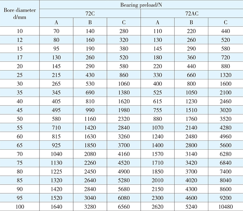
For a matched set of two or more than two bearings, adequate preload has to be attained after mounting and fastening. The proper selection of the preload can give higher rigidity, lower temperature and higher working accuracy to the spindle system of the bearing arrangement. Three bearing preload grades are specified: (A) light preload, (B) medium preload, and (C) heavy preload, subject to customer’s actual demands on the specific spindle system. Preloading values for different series duplex bearings matched in face-to-face or back-to-back arrangement are listed in Tables 3 to 6.
With a contact angle of 40°(suffix B), single row angular contact ball bearings are manufactured in two designs. The first design of these bearings are used in the bearing arrangement which only needs one of the bearing in one individual arranging position. The second design of those bearings are suitable for the bearing arrangement which needs two or more than two adjacent bearings to be mounted in any matched set (universal matching).
The single row angular contact ball bearings of universal design, intended for universal matching, are specially tailored to match the adjacent bearings as a set in any bearing arrangement, and the predetermined clearance and even load distribution can be attained without the help of shims or others. The bearings of universal design are indicated with the suffix CB, where C representing axial clearance. B representing clearance grade. The bearings of smaller or larger clearance are also supplied according to customer’s specified requirements. For the preloaded bearings, the light, medium or heavy preload is identified by suffix GA, GB or GC. (G represents preloaded or negative clearance). When ordering the bearings of universal design, for example 7206BTNGB, the number of required single bearings has to be indicated.
Table 1. Different arrangements of two or more than two bearings of single row angular contact ball to be matched
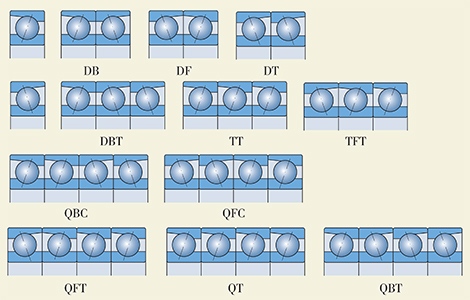
Table 2. Structure features of duplex bearings
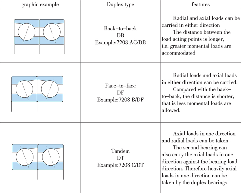
Table 3 Bearing preload
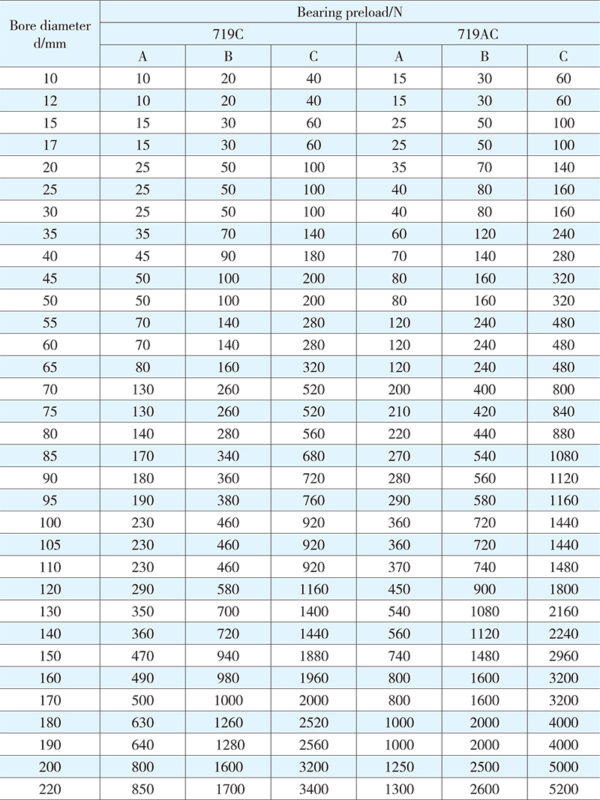
Table 4 Bearing preload
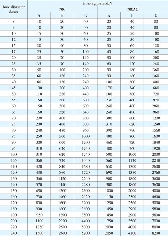
Table 5 Bearing preload
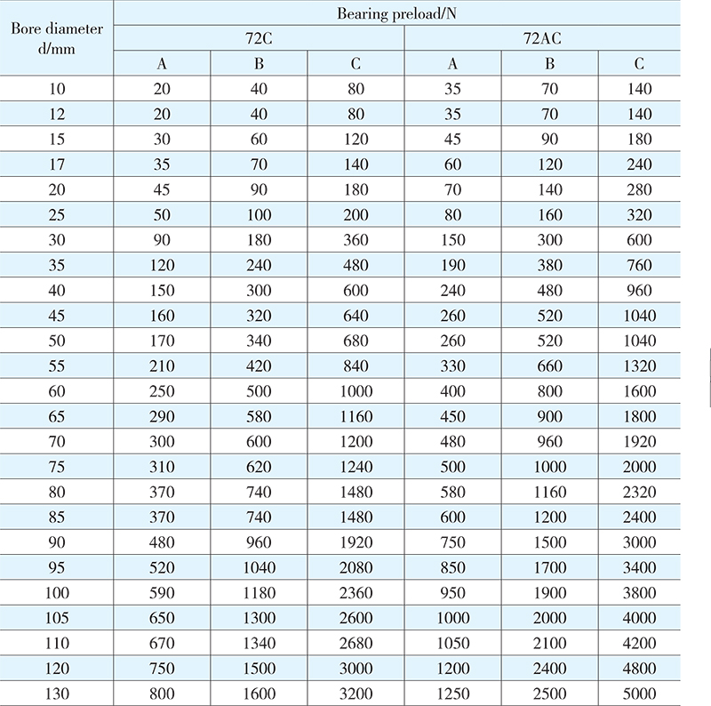
Table 6 Bearing preload
3. Dimensions
The boundary dimension of single row angular contact ball bearings given in the bearing tables are in conformity with ISO15.
4. Angular misalignment
Single row angular contact ball bearings have comparatively limited ability to moderate some errors in alignment, and the conditions are so complex as for deep groove ball bearings.
Where these bearings are mounted in pairs, especially in back-to-back arrangement, the angle misalignment, and has to be a burden and to become an additional force on the balls and raceways, that is, greater loads on the balls, incremental stress in the cage and shortened life of the bearing may level.
Any angle misalignment will result in the in create of noise during bearing operation.
5. Tolerances
HRB standard single row angular contact ball bearings are mainly produced in accordance with the requirements of normal tolerances class P0. On customer’s demand, the products of tolerances classes P6, P5,P4 and P2 are also supplied. The high speed and ultra-high speed bearings to tolerance classes P4 and higher can be manufactured, i.e, the products upto special tolerance class P4A are available as well. Those bearings of a contact angle of 40°, used in universal pairs, are produced on the basis of tolerance class P6, without the angle suffix, tolerances class P5 available as well.
Internal clearance
For paired single row angular contact ball bearings, axial clearance is only obtained by mounting and controlled by the adjusting distance between the bearing to another bearing, and a counteractive location of the bearing pair is generated.
Identified by suffix CA, CB or CC, bearings of universal design are able to be mounted in a set of two or more than two bearings adjacent in any arrangement. But those preload design bearings will suffix GA,GB or GC can only be mounted in pair, otherwise, the preload value could be increased greatly.
Values for internal clearance indicated by suffix CA, CB or CC are obtained from the following table, valid for face-to-face or back-to-back paired bearings before mounting and under zero load. Values for preload indicated by suffix GA,GB or GC are given in the next table, valid for the bearings before mounting.
Axial internal clearance in 72B or 73B series single row angular contact ball bearings, paired in face-to-face or back-to-back arrangement after mounting
![]()
Radial internal clearance≈0.85 axial internal clearance
Bearing arrangement
Where a bearing arrangement is to be made, the characteristics of single row angular contact ball bearings must be considered. Because of their interior structure, these bearings can not be adopted singly, so that they have to be mated against a second bearing or a second bearing set.
Axial preload in 72B or 73B series single row angular contact ball bearings, paired in face-to-face or back-to-back arrangement after mounting
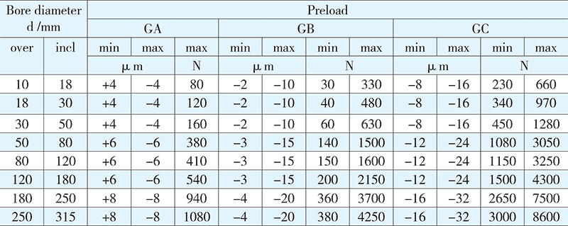
As mentioned in the paragraph “internal clearance”, in a bearing arrangement the two single row angular contact ball bearings have to make mutual accommodation so as to attain to the expected running clearance or preload.
For bearings of universal design, there is no need to adjust mounted bearing pairs, because a proper selection of the preload or axial internal clearance grade and the fit between the bearings to bearing housing and shaft is enough to reach the required preload or running clearance.
In general, correct selection and adjustment of axial internal clearance or preload can enhance a bearing and its matched set to work well. If the operating clearance of a bearing is too large, its load carrying capacity could become lower, conversely, too much of preload could cause more frictional resistance, running temperature generation and bearing life reduction. Precaution: unless Fa/Fr ≥ 1, single row angular contact ball bearings with contact angle of 40°will fail to reach a satisfactory rolling status.
For back-to-back or face-to-face bearing sets, the axial load mainly in one direction must be taken particular precautions. Under such conditions, the appearance of improfer rolling action of the non-loaded bearing will lead to noise raised, lubricating oil film broken and cage stress increased. For the matched bearing set, the better the less clearance in running is. More details should be consulted with HRB service department.
Minimum rolling bearing load
In order to keep proper running of bearings, the minimum required loads must act on the bearing at least, also including angular contact ball bearings, or else at high speed running destructive sliding of the balls relative to the raceways would arise from the mass forces of the balls and cage and the frictional resistance of the lubricant.
Considering such a situation, the minimum required load for single bearing or matched bearing sets in tandem is estimated from the equation:
Fam = Ka×Co/1000×(n×dm/100000)2
For matched bearing sets in back-to-back or face-to-face, the minimum required load is estimated from the equation:
Frm = Kr(γn/1000)2/3(dm/100)2
where:
Fam: minimum axial required load, N
Frm: minimum radial required load, N
C0: basic static load rating, for single bearing or matched bearing set, N
Ka: minimum axial load factor
Ka=1.4, for 72BTN series bearings
Ka=1.2, for 72BM series bearings
Ka=1.6, for 73BTN series bearings
Ka=1.4, for 73 BM series bearings
Kr: minimum radial load factor
Kr=80, for 72BM series bearings
Kr=95, for 72BTN series bearings
Kr=90, for 73BM series bearings
Kr=100, for 73BTN series bearings
γ: kinematic viscosity of oil at operating temperature, mm2/s
n: bearing speed, r/min
dm: bearing mean diameter = 0.5(d+D), mm
In general, the bearing supporting weight adding the external forces always goes beyond the minimum required load. If not, an axial preload has to be exerted to single bearing or bearing sets in tandem arrangement when mounting, for example, adjusting the inner ring closed to the outer ring or enforcing them together with a spring. For those matched bearing sets in back-to-back or face-to-face arrangement, an additional radial load must be exerted, for example, increasing belt tension.
Equivalent dynamic bearing load
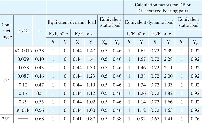
1. The equivalent dynamic bearing load, contact angle 15°or 25°, is obtained from the following equation:
P = XFr + Y1Fa
P0 = X0Fr + Y0Fa
P0 = Fr for P0<Fr
2. Values for X, Y, X0 and Y0 are listed in the following table.
Equivalent load calculation for bearings with a contact angle of 40°:
(1) Equivalent dynamic load:
Single bearings or tandem (DT) arranged bearing pairs:
P = Fr for Fa/Fr ≤ 1.14
P = 0.35Fr + 0.57Fa for Fa/Fr>1.14
Back-to-back (DB) or face-to-face (DF) arranged bearing pairs:
P = Fr + 0.55Fa for Fa/Fr ≤ 1.14
(2) Equivalent static load
Single bearings or tandem (DT) arranged bearing pairs:
P0 = 0.5Fr + 0.26Fa
P0 = Fr for P0<Fr
Back-to-back (DB) or face-to-face (DF) arranged bearing pairs:
P0 = Fr + 0.52Fa
The basic load rating of a matched bearing pair may be regarded as that of the bearing, obtained from the bearing table.
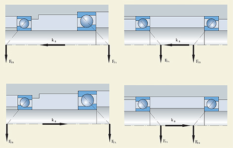
Shown in the diagram, in the bearing arrangement there is an interaction between the two bearings, so that the influence of the radial loads and the additional axial load has to be considered in the calculation of the axial load.
Basic load ratings for matched angular contact ball bearings (an contact angle 15°or 25°)
1. Dynamic load rating
DB, DF, DT Cr x 1.62
TBT, TFT, TT Cr x 2.16
QBC, QFC, QT Cr x 2.64
QBT, QFT
2. Static load rating:
DB, DF, DT Cr x 2
TBT, TFT, TT Cr x 3
QBC, QFC, QT Cr x 4
QBT, QFT
Limiting speeds of paired bearing sets
Bearing sets in DT arrangement, or in DB and DF arrangements subjected to light grade preload (A grade) can reach an operating speed of 20% reduction. The bearing set of three bearings matched can reduce the speed by 35%. The bearing set of four bearings or the bearing set with mixed grade preloads may be consulted with HRB technology department for its limiting speed.
Catalog of Single-row Angular contact ball bearings